ENGINEERING NOTEBOOK / 030
Concept Design
The Cantilever Chainstay
A carbon-fibre racing bicycle built around a single cantilever chainstay, belt-driven transmission and integrated suspension, exploring the trade-offs between visual simplicity and mechanical performance.
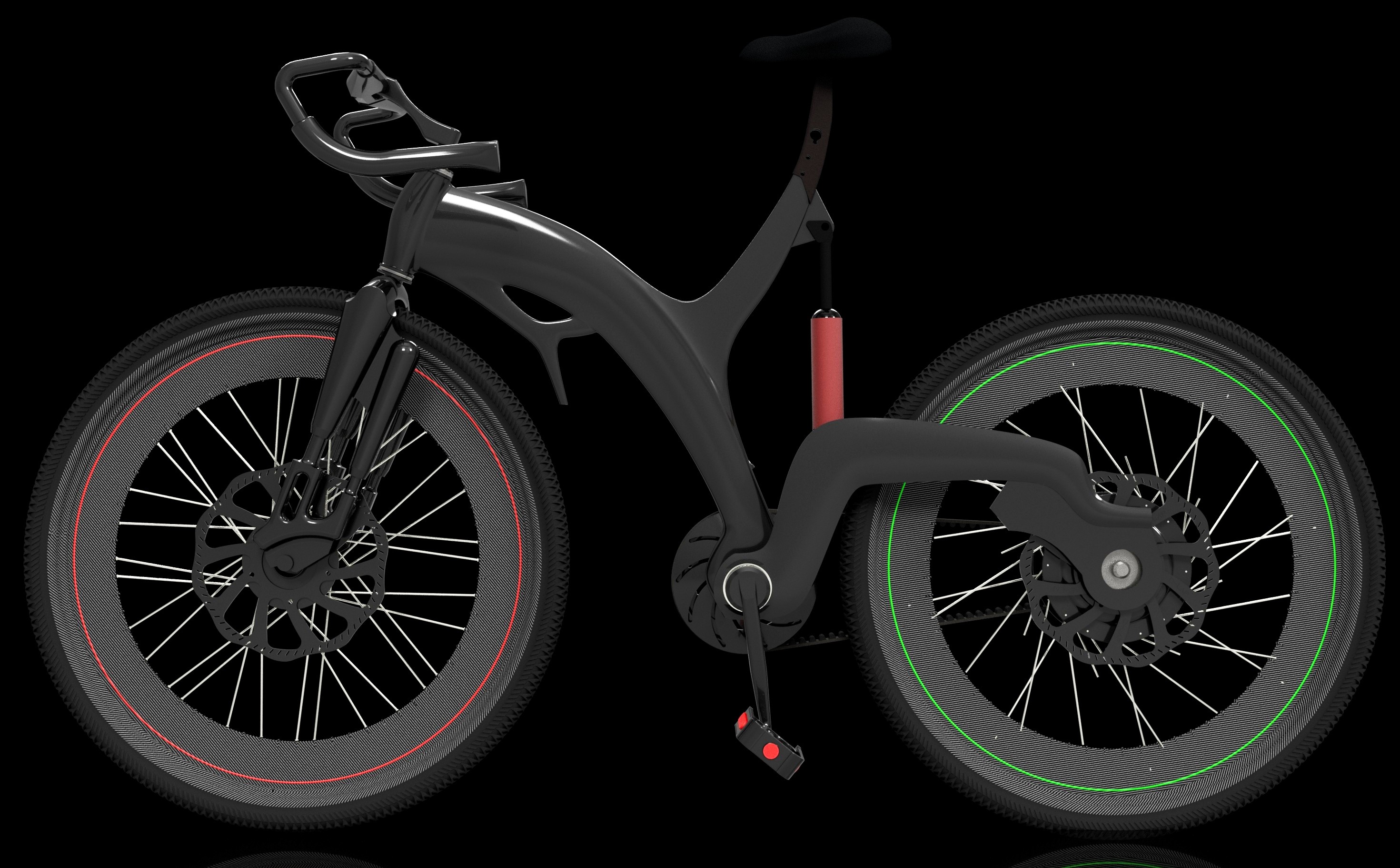
The Cantilever Chainstay
Sometimes a design starts with a question about performance.
Other times, it starts with a question about form.
This one started with a simple idea:
What would a racing bicycle look like if I removed one of the conventional chainstays?
I wanted to explore a lightweight carbon-fibre bicycle with a single rear support beam, a belt-driven transmission and a compact suspension system.
The result was a machine that looked more like a sculptural engineering object than a conventional racing bicycle.
Clean.
Minimal.
Unconventional.
And mechanically, not without its compromises.
The frame looked beautiful at first glance. The carbon-fibre body gave the bicycle a naturally refined appearance, while the cantilevered rear structure created a distinctive relationship between the frame and the rear wheel.
But the more I examined the architecture, the more interesting the engineering questions became.
How would the rear axle handle the loads?
What would the belt drive do to power transmission?
And could a single spring-damper unit provide meaningful suspension without compromising the structure?
360° OF THE CONCEPT
Before breaking the bicycle down into its individual systems, this is the complete design as I originally imagined it.
A lightweight carbon-fibre racing bicycle intended for smooth terrain, built around a different structural and drivetrain architecture.
360° render of the cantilever chainstay racing bicycle concept.
01 — A SINGLE CHAINSTAY
The first major decision was to rethink the rear structure.
Instead of using two conventional chainstays extending toward the rear axle, I wanted to explore a single beam supporting the wheel through a cantilevered arrangement.
The objective was not simply to remove a component.
I wanted the rear structure to become a defining part of the bicycle's identity.
The beam would be visible.
The rear wheel would appear to extend from a more concentrated structural arrangement.
And the frame could develop a cleaner, more sculptural silhouette.
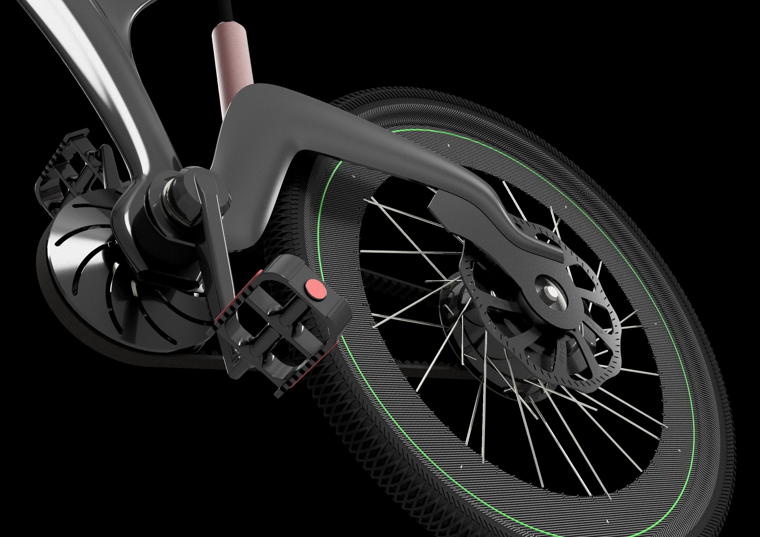
The single-beam rear architecture became one of the defining features of the concept.
There are potential advantages to this approach.
The visual architecture becomes simpler.
The structural arrangement can be designed around a more concentrated load path.
And the reduced number of visible members creates opportunities for a different kind of industrial design.
But the structural consequences cannot be ignored.
A single support member may experience significant bending and torsional loading, particularly under braking, cornering and asymmetric rear-wheel loads.
The axle support, frame stiffness and fatigue performance would all require proper analysis.
The design works as a CAD concept.
That does not automatically establish that it is suitable for racing.
02 — CARBON FIBRE AS THE BODY
The carbon-fibre body was an important part of the design from the beginning.
I wanted the bicycle to be lightweight, but I also wanted the frame to have a form that would be difficult to achieve through conventional tube-based construction.
Carbon fibre provides opportunities to combine structural surfaces, carefully oriented laminates and integrated geometry.
The objective was to create a body that could appear continuous and intentional rather than assembled from disconnected components.
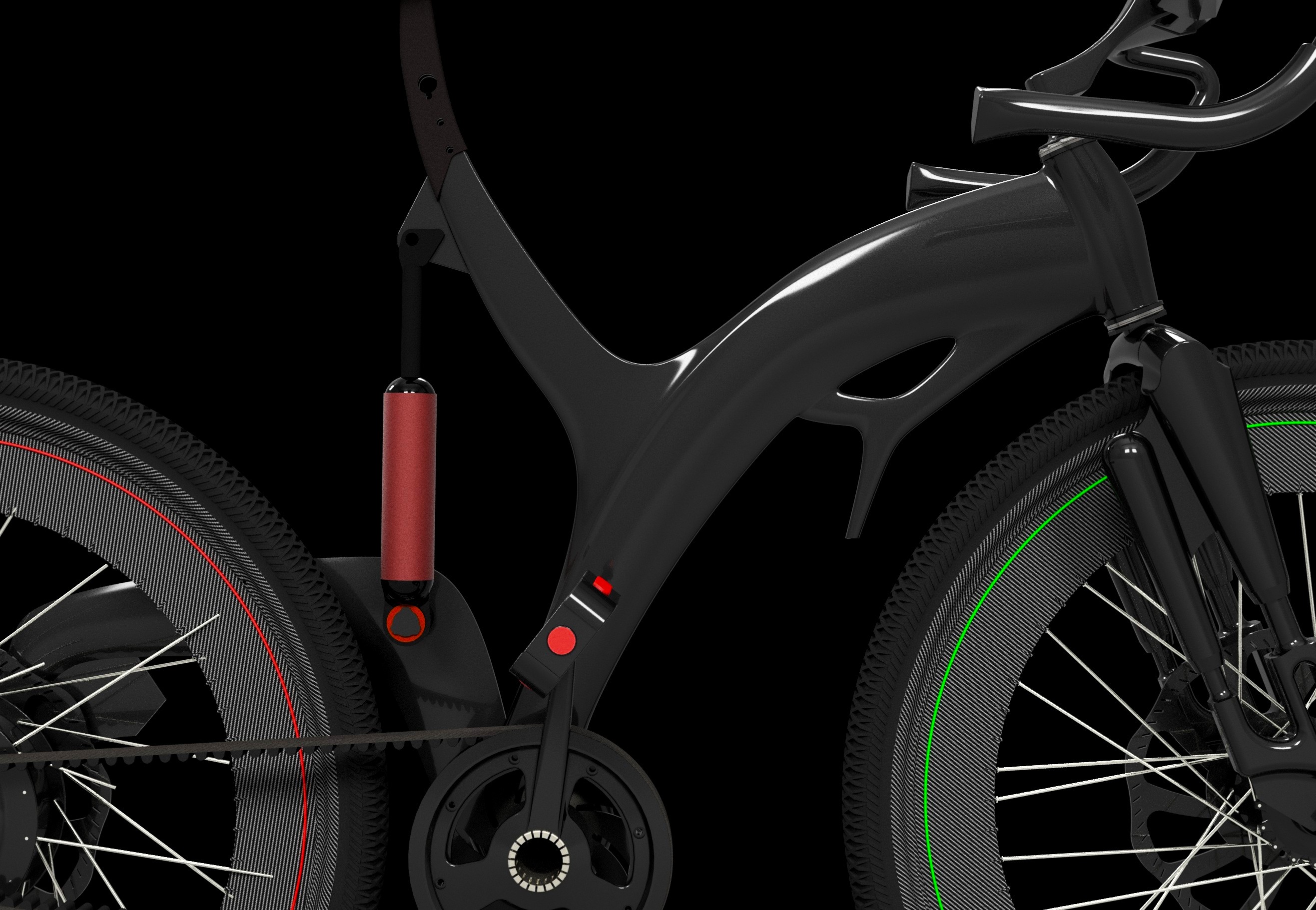
The carbon-fibre body gives the concept its sculptural character.
A lighter bicycle can offer advantages during acceleration and changes in speed.
However, mass reduction must be considered alongside stiffness, durability, manufacturing constraints and the actual requirements of the rider.
A frame can be lightweight without having adequate stiffness.
It can also be structurally strong in one load case while remaining vulnerable to fatigue or impact.
That is the part of carbon-fibre design that interests me.
The material offers considerable freedom.
But the freedom comes with responsibility for how the structure is engineered.
03 — BELT DRIVE INSTEAD OF A CHAIN
The next major decision was the drivetrain.
I chose a belt drive instead of a conventional bicycle chain.
At a glance, the belt provides a cleaner visual arrangement.
There is no conventional chain lubrication requirement, and a properly designed toothed belt system can offer quiet operation and reduced maintenance.
For a concept focused on a minimal appearance, the belt also fits naturally into the overall design language.
But this is where the project becomes mechanically interesting.
A clean drivetrain is not necessarily an efficient drivetrain.
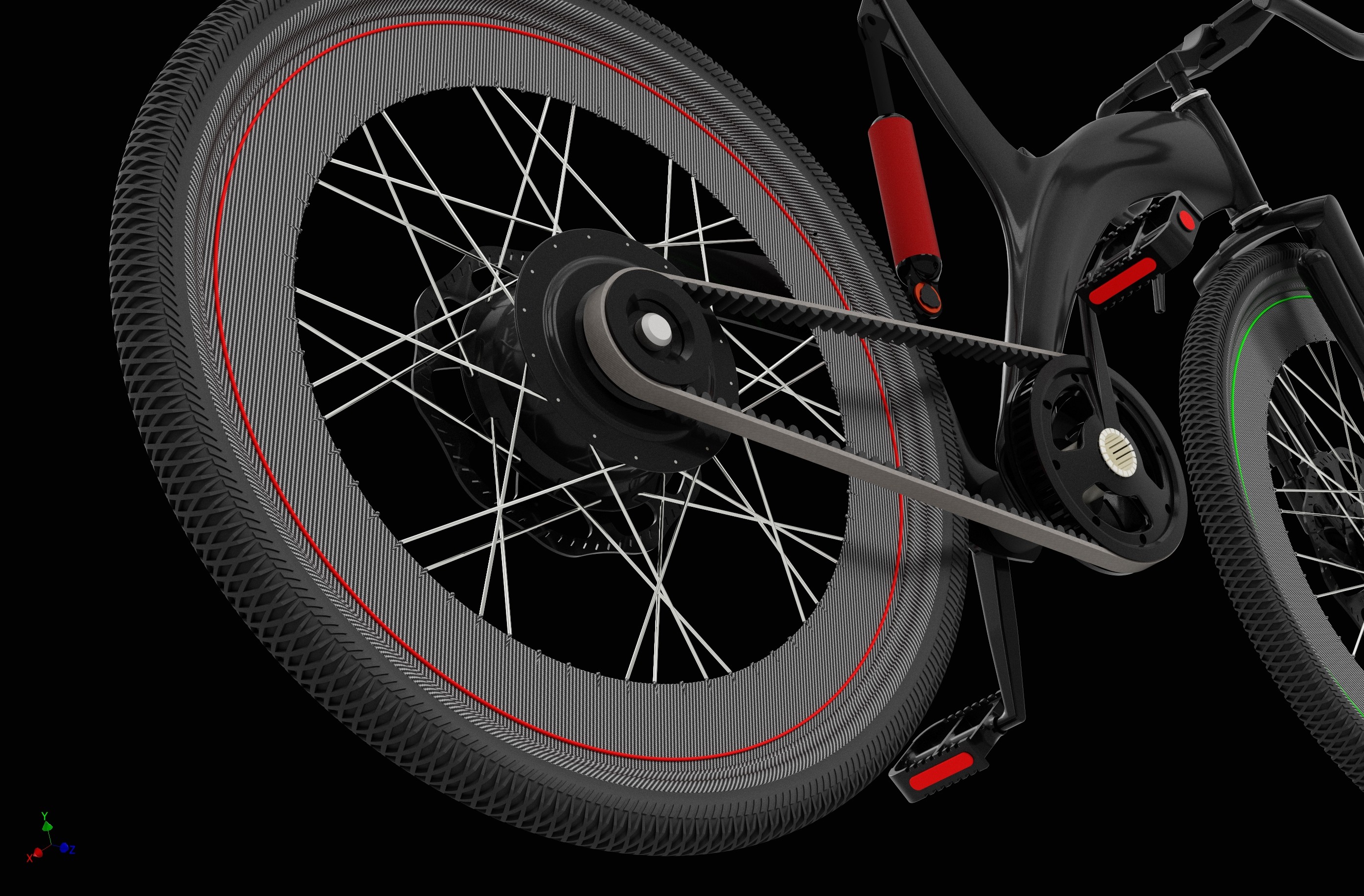
A close-up of the belt-driven transmission.
The belt introduces a different set of engineering considerations.
Elastic deformation.
Hysteresis.
Belt tension.
Sprocket alignment.
Bending losses.
And the way torque is transferred through the system.
The belt's elasticity was one of my concerns.
Under loading, the belt can deform, and energy can be dissipated through material hysteresis and other mechanisms. The magnitude of the losses depends on the specific belt, sprockets, tension, alignment and operating conditions.
I initially considered whether these effects could account for a substantial portion of the total drivetrain losses.
However, I have not experimentally established a 30% loss figure for this design.
That would require actual testing.
The question is important because this is a racing bicycle.
The rider's power must be transferred efficiently to the rear wheel.
A lightweight carbon-fibre body can reduce mass, but it cannot automatically compensate for drivetrain losses.
04 — THE POWER TRANSMISSION TRADE-OFF
The belt drive introduced a trade-off that I could not ignore.
On one side, the drivetrain supports the visual simplicity of the concept.
On the other, racing places a premium on efficient power transfer.
A conventional chain can achieve high transmission efficiency under suitable conditions. A belt drive can also perform efficiently, but the actual result depends on the complete system rather than the belt alone.
This is where the design needs more than a render.
It needs measurements.
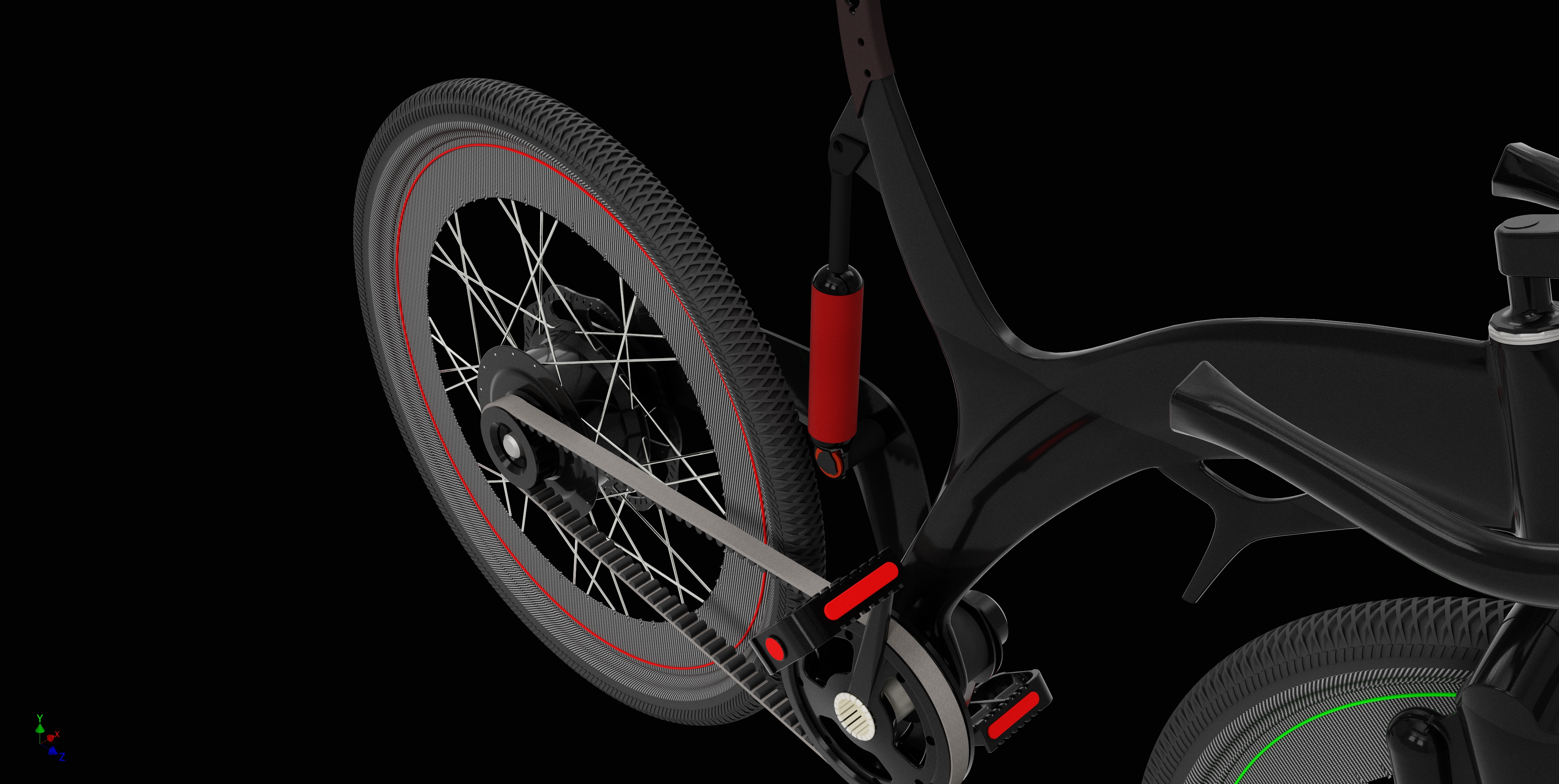
The belt, rear wheel and surrounding structure.
If I were to continue developing the bicycle, I would want to compare the drivetrain against a conventional chain system under equivalent operating conditions.
The investigation would include:
- Input and output torque.
- Cadence and rider power.
- Belt tension.
- Sprocket alignment.
- Transmission temperature.
- Efficiency across different loads.
The aim would be to establish whether the chosen architecture provides an acceptable performance trade-off.
The drivetrain should be evaluated as an engineering system, not judged solely by its appearance.
05 — ONE ISOLATION UNIT
The bicycle features a single suspension unit containing a spring and damper.
The unit is mounted between a point a short distance below the seat and a location along the chainstay, approximately one-third of the distance from the pedal pivot region toward the rear.
I wanted to explore whether a compact isolation mechanism could be integrated into the frame without disrupting the overall silhouette.
Instead of several visible suspension components, the design concentrates the mechanism into one unit.
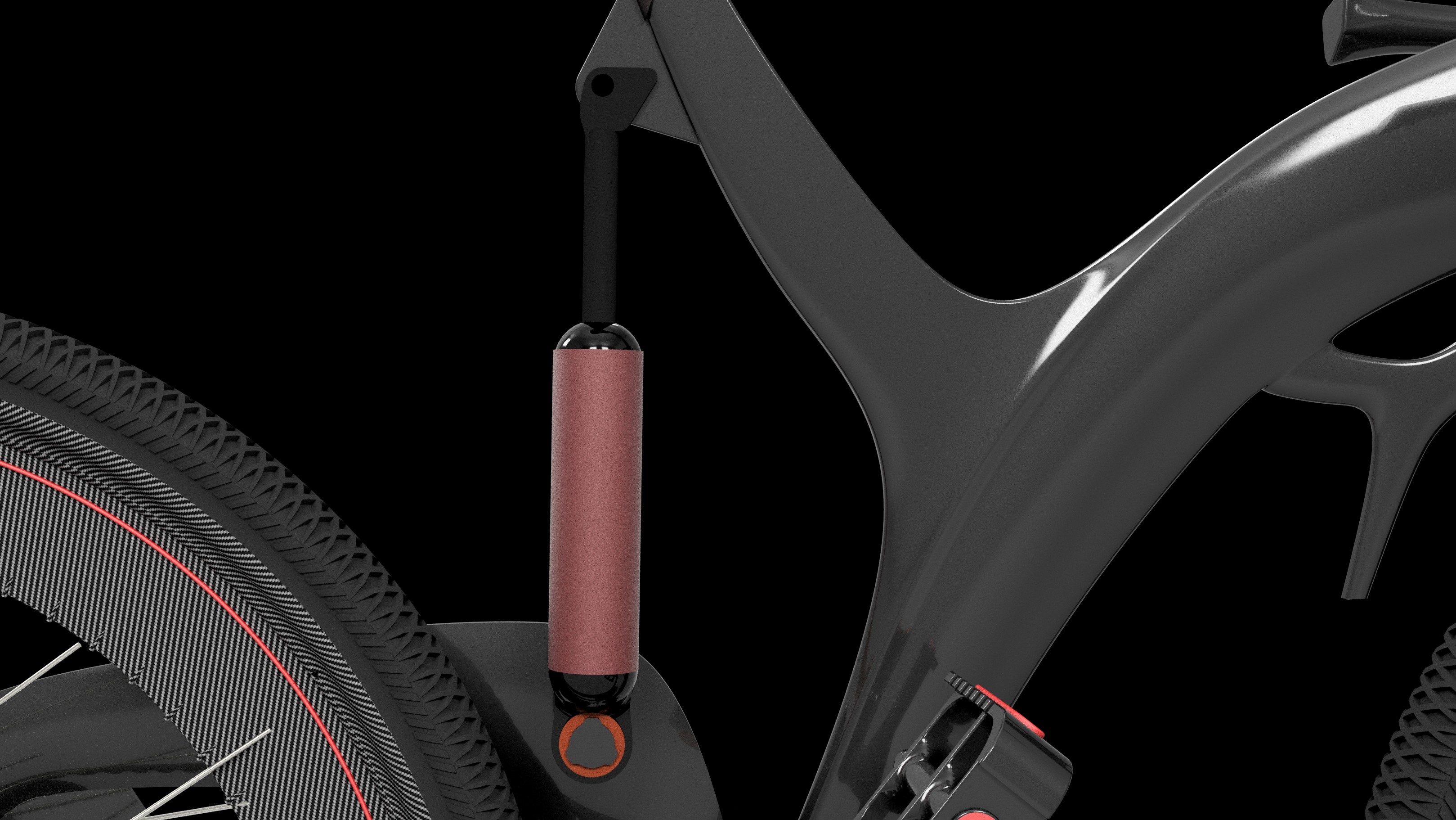
The spring-damper unit integrated into the bicycle's rear architecture.
The mounting locations influence how the suspension behaves.
The distance between the pivot and the damper attachment point affects the mechanical leverage ratio.
That ratio determines how wheel movement translates into spring compression and damper displacement.
It also influences the forces transmitted through the attachment points and the surrounding frame.
This means the suspension cannot be considered independently of the carbon-fibre structure.
The mounting region must withstand the loads generated during operation.
The next step would be to establish the suspension kinematics, calculate the leverage ratio and assess the loads through the full range of movement.
06 — THE CANTILEVER REAR AXLE
The rear axle was another area where the visual concept and mechanical requirements came into tension.
The cantilever arrangement contributes to the bicycle's distinctive appearance.
At a glance, the rear wheel seems to be supported through a minimal structural connection.
But the axle support is not simply a visual element.
It is a load-bearing component.
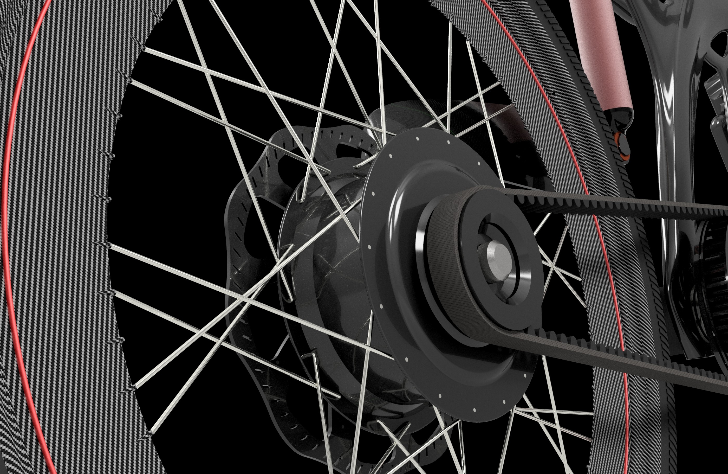
A close-up of the cantilever rear axle arrangement.
The rear support must be considered under several loading conditions.
Vertical loads from the rider and terrain.
Lateral loads during cornering.
Braking forces.
Drive torque reactions.
And transient loads caused by uneven surfaces.
A single-sided support can introduce asymmetric loading and additional bending demands.
The exact behavior depends on the geometry, axle design, bearings, material properties and load cases.
The arrangement works as a concept.
But if I were to take this design toward fabrication, the rear axle would require more detailed structural analysis.
The challenge would be to preserve the visual identity while developing a support structure with adequate stiffness, strength and fatigue resistance.
07 — THE RELATIONSHIP BETWEEN FORM AND FUNCTION
One of the things I find most interesting about this project is the way the design decisions influence one another.
The carbon-fibre body creates the overall form.
The cantilever chainstay changes the structural load path.
The belt drive influences the drivetrain architecture.
And the suspension system introduces another set of loads and geometric constraints.
None of these systems exists in isolation.
A change to the rear beam can affect the suspension.
A change to the belt arrangement can affect the frame packaging.
A change to the axle support can affect stiffness and mass.
The design process becomes an exercise in balancing objectives.
The objective is not simply to make the bicycle as light as possible.
Or as visually striking as possible.
Or as mechanically simple as possible.
It is to determine whether the combined system can satisfy the requirements of the application.
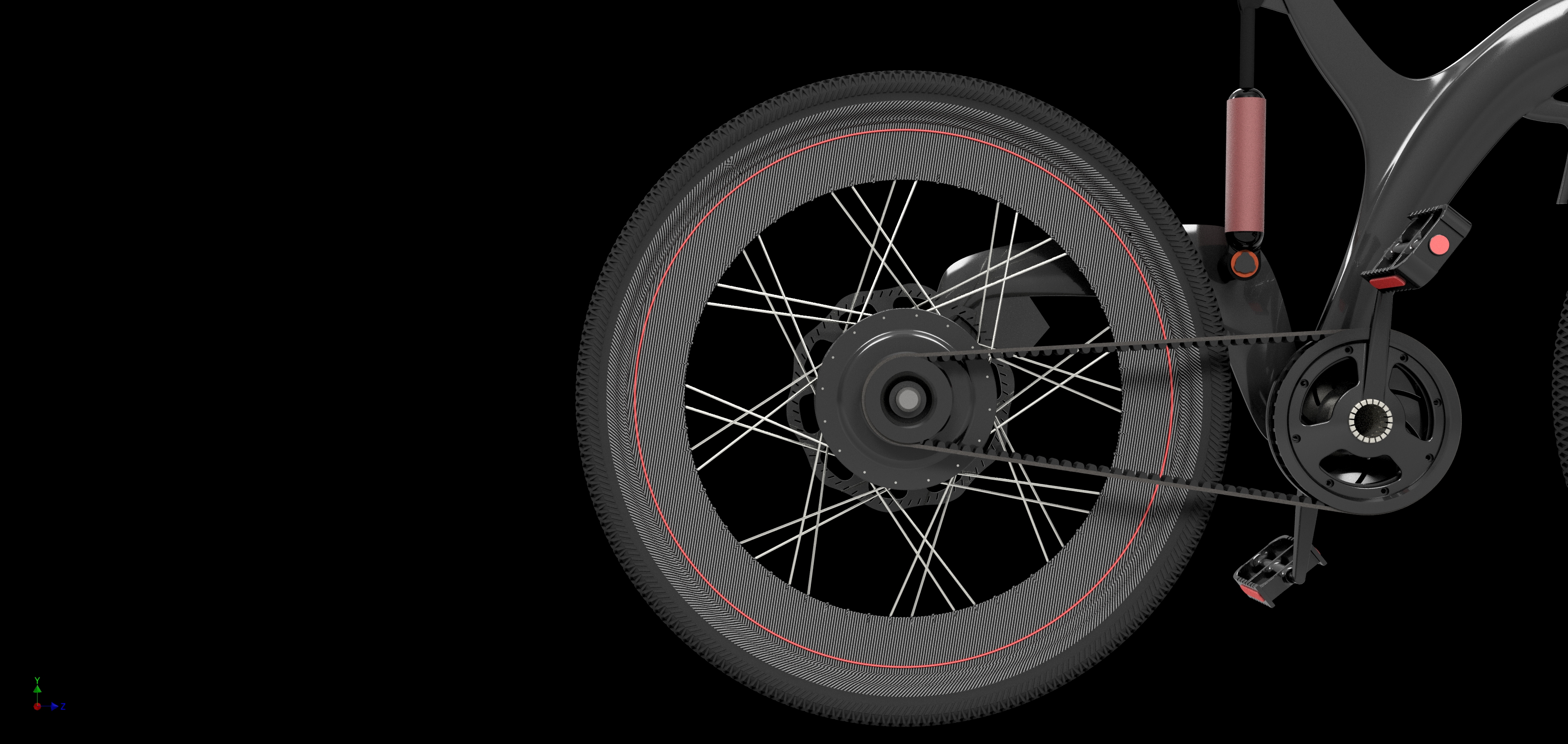
The relationship between the chainstay, pedal assembly and rear wheel.
08 — WHY THE DESIGN IS INTENDED FOR SMOOTH TERRAIN
The bicycle was conceived as a racing machine for smooth terrain.
That context matters.
The loads, suspension requirements and durability expectations of a bicycle designed for smooth roads differ from those of a bicycle intended for aggressive off-road use.
A design optimized for one application should not automatically be assumed to perform well in another.
The lightweight structure, integrated suspension and unconventional rear axle were developed with a particular use case in mind.
The next stage would be to establish the relevant operating loads and determine whether the architecture can meet them.
This would include an assessment of frame stiffness, rear axle deflection, suspension behavior and drivetrain performance.
The design intention provides a starting point.
The engineering analysis would determine how well the concept meets it.
09 — THE DESIGN PROCESS
The bicycle was developed through CAD, with the overall form guiding the development of the individual components.
I began with the architecture.
The frame.
The rear support.
The drivetrain.
The suspension.
And the relationship between the rider and the rear wheel.
The process moved between:
IDEA → SKETCH → FORM → CAD → SYSTEM INTEGRATION → RENDER
The objective was to understand how the individual components could come together as one machine.
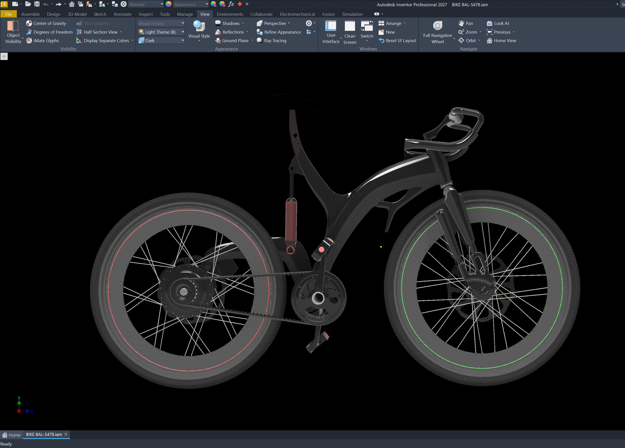
The CAD environment used to develop the bicycle concept.
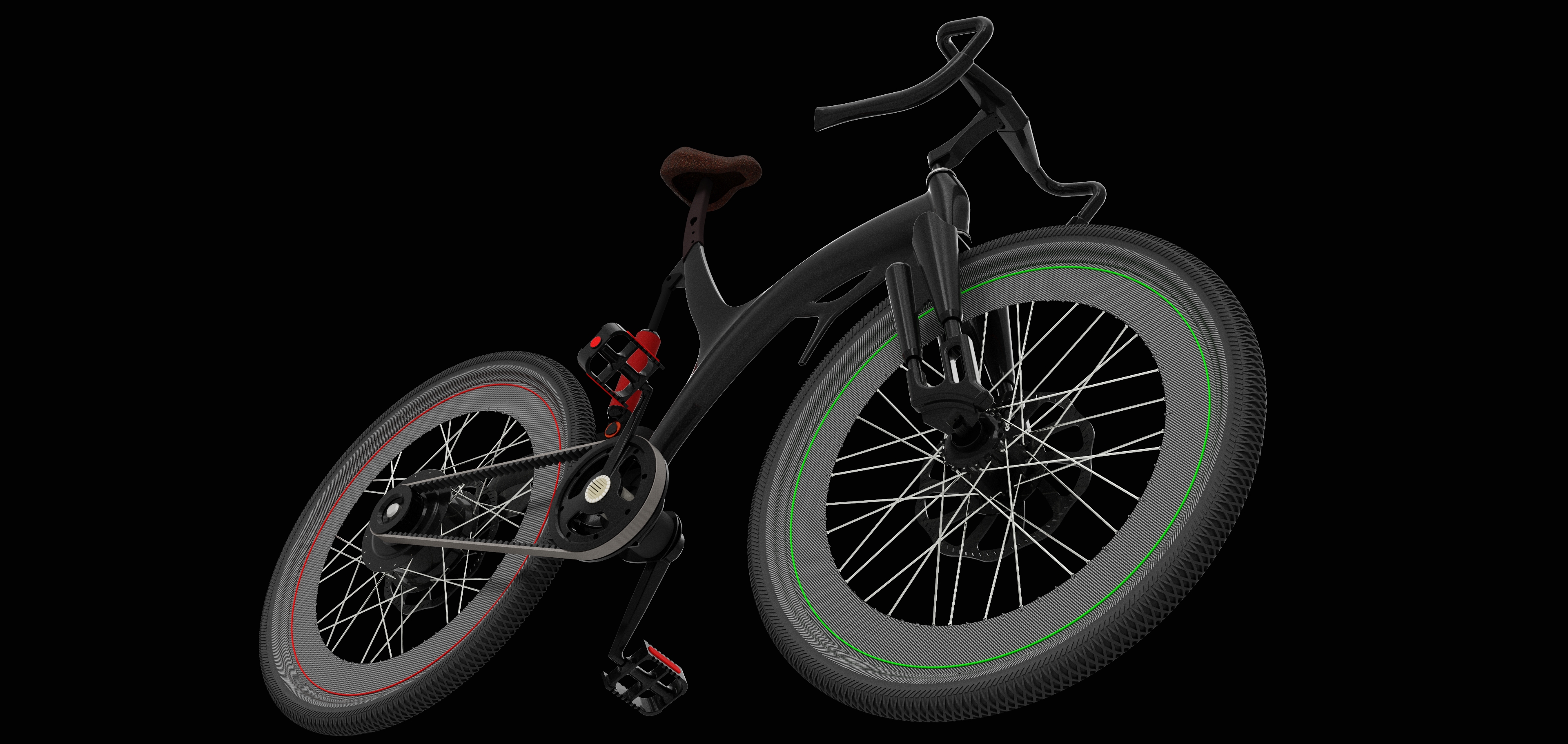
Exploring the overall form and proportions.
The renders helped me evaluate the design as a complete object.
The proportions.
The visual balance.
The relationship between the frame and the wheels.
And the way the suspension and drivetrain fit into the architecture.
But rendering is only one part of the design process.
A complete engineering development would require detailed component design, structural calculations, simulation and physical validation.
10 — WHAT I WOULD CHANGE NOW
Looking at the design now, I can identify several areas that would need further development.
The rear axle support would require structural and fatigue analysis.
The belt drive would need efficiency testing under realistic loads.
The suspension would need a defined wheel travel path and leverage ratio.
The carbon-fibre frame would require a proper laminate design and assessment of local load concentrations.
And the entire system would need to be evaluated against the requirements of racing use.
The bicycle looks close to a finished product in the renders.
But the engineering work is not finished.
That distinction matters.
A CAD model can demonstrate geometry and mechanical relationships.
It cannot, by itself, establish structural safety or performance.
11 — WHY I STILL LIKE THE DESIGN
Despite the compromises, the project remains an interesting design exercise.
It forced me to reconsider the bicycle as a complete system.
The rear structure became a visual feature.
The carbon-fibre body became both a structural and aesthetic element.
The belt drive introduced a different transmission architecture.
And the suspension became part of the frame's overall design rather than an isolated component.
The bicycle is not a conventional racing frame with a few components replaced.
It is an attempt to rethink the relationship between form, structure and mechanical function.
That is what I was really exploring.
Not simply a new bicycle.
A different way of arranging the machine.
Notebook 030
The most interesting part of a design is sometimes the compromise you discover after the render is finished.
END OF NOTEBOOK 030
BACK TO
THE NOTEBOOK
Every finished design leaves another question behind.
RETURN TO JOURNAL